

HDD LED off Xbox HD
I don't know what it is, but I like HDD LEDs. Maybe it comes from a deep seated need to know exactly what's going on with my hardware at all times. I love watching my RAID when it's accessing data. Anyhow, most SCSI and decent HDs have pins that you can string HDD LEDs off of. Most if not all IDE drives do not. However, pin 39 is the HDD activity pin on an IDE pinout. So in theory, you should be able to string an LED directly off that pin if there is no access to it on the HD PCB itself. Let me also say that the Xbox is a *GREAT* console. It has the ability to play divx, mp3s, emulators, etc. This mod was important to me because I upgraded the 9gb HD to an 80gb, and when I'm ftping games, mp3s or movies to it, I'd like to be able to see from across the room when it is finished. I wasn't simply adding an LED to a regular Xbox.

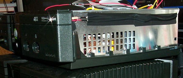
The PCB on this 80GB Western Digital HD is inverted and rests parts side up to protect the components. Even after scratching the laminant off, solder wasn't sticking to the leads, so I took the PCB off and flipped it over, soldering directly to the +5v pin coming in from the molex [Above]. Pin 39 was behind pin 40 (the last pin) and really difficult to reach. Not wanting to take any chances with a decent HD, I taped off and reassembled the PCB. I then went at the IDE cable directly [below].

This was a lot easier, and IDE cables are super cheap. I actually think you should just solder to the +5v of the molex power cable instead of soldering directly onto the HD PCB, it may look dumb, but it's a lot safer. It took some work with an exacto knife to get a lot of the wire exposed, but it didn't take longer than 3-4 mins. These two wires go to a little three pin connector in the back of the xbox. (couldn't find a two pin connector)
Here you can see the side, notice the bling of the shiny new LED (that aint photoshop either). OK, the +5v we strung off the HD has a little too much power for an LED, so I knocked it down with a 220ohm resistor. [pictured above] Don't get confused, the red wire you see is not the +5v. Now LEDs have two pins, the Anode and the Cathode. The Anode is the longer pin connects to the 220ohm resistor and then to the +5v from the HD. The Cathode side goes to pin 39 of the HD. Be sure to use shrink tubing or electrical tape to prevent a short. Drill a hole wherever you want it, and pop the sucker in. String the wires round to the back, and plug them into the other two. (if you are making a plug)

Here's what it should look like when you're done, something like this, more depending on what kind of bezel you buy.
Here's a list of the parts:
[RadioShack]
220ohm resistors
Red LED with holder
[Jameco]
Soldering Iron